
Surface Finish on Aluminum: What Ra You Can Actually Hit, and What the Print Is Really Asking For
By Faramir
Every shop has had this argument. The print says 63 Ra, the part measures 90, and somebody opens a feed and speed calculator to fix it. Sometimes that works. More often the feed was never the problem, and dropping it makes the finish worse, because you have walked the chip thickness down into the region where the edge stops shearing and starts plowing. The theoretical finish formula is real geometry worth knowing cold, but what it computes is a lower bound on the scallop height the tool nose leaves behind. It does not know your edge is worn, your holder has half a thou of runout, or that you are cutting 6061-T651 with a coating that likes to weld aluminum to itself. Here is what Ra you can actually hit by process, the formulas that set the floor, why aluminum fights you, and how to read a finish callout for what it is really asking.
In Short
- →Ra = f^2 / (32 x r) is a floor, not a forecast. It measures only the scallops the nose radius leaves behind, and those are frequently the smallest thing on the trace.
- →In milling the feed term is nearly irrelevant. A 0.500 in cutter at 0.004 in per tooth leaves theoretical feed marks about 8 uin tall. Half a thou of runout at the tip is 500 uin.
- →Most finish failures on aluminum are built-up edge, a dull or unpolished edge, runout, or deflection. Feed math is the last thing to touch, not the first.
- →The Aluminum Association machinability letters grade chip form and achievable finish, not speed or power: 7075-T6 and T651 are rated B, 6061-T6 and T651 are rated C.
- →Ra and Rz are not linked by a fixed ratio, so a print calling out both, with numbers taken from different tables, can be impossible to satisfy at once.
Ra Is an Average, and That Is the Whole Problem
Ra is the arithmetic mean deviation of the roughness profile from its mean line, taken over a defined length after form and waviness are filtered out. Because it averages absolute values, it is deliberately blind to individual features. One deep drag mark from a recut chip barely moves it, and a surface that is uniformly hazy from smearing can read the same as one that is optically bright with a gouge in it. That blindness is why Ra became the universal number and why it rarely captures what the designer was actually worried about. To move between Ra, Rz, RMS, and CLA units, use /resources/surface-finish-converter. To ask what a given tool and feed will actually produce, a different question entirely, use /resources/surface-finish-predictor.
125 uin = 3.2 um
The default machined finish on most prints
63 uin = 1.6 um
Requires a deliberate finish pass
32 uin = 0.8 um
Requires tool and setup control
16 uin = 0.4 um
At or past the edge of ordinary milling
The Geometry That Sets the Floor
In turning, the tool nose is an arc of radius r stepped along the workpiece by the feed f once per revolution. What it leaves is a row of scallops whose height is pure geometry: no material properties, no tool condition, no spindle. Just a circle and a step. The exact sagitta of that scallop is r minus the square root of r squared minus f squared over 4, but nobody uses the exact form, because for any sane ratio of feed to nose radius the approximation below is within a fraction of a percent and far easier to invert.
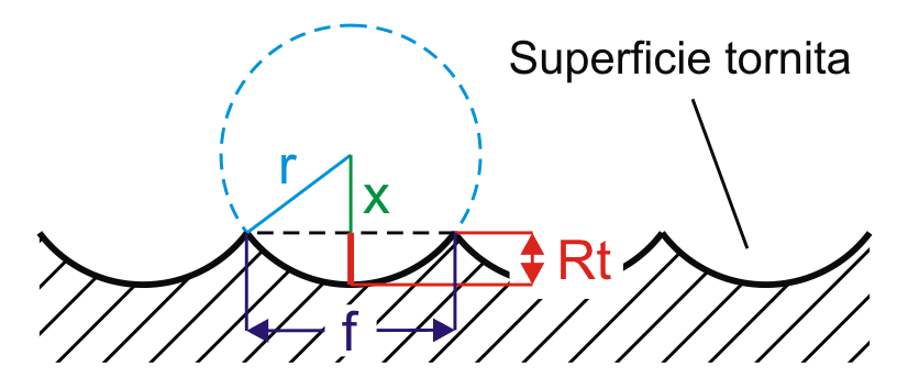
Formula One: Peak to Valley Height
Theoretical peak-to-valley height (Rz, also written Rt or Rmax)
Rz = f^2 / (8 x r)
= 0.008 in/rev with a 1/32 in nose radius: Rz = 0.000064 / (8 x 0.03125) = 0.000256 in = 256 uin = 6.5 um
- f
- Feed per revolution in inches (feed per tooth in milling)
- r
- Tool nose radius or corner radius in inches
- Rz
- Scallop height in inches. Multiply by 1,000,000 for microinches
- exact form
- Rz = r - sqrt(r^2 - f^2/4), which the 8r approximation tracks closely below about f = r/2
Formula Two: Turning That Into Ra
For a periodic profile of near-triangular scallops the arithmetic average works out to about a quarter of the peak-to-valley height. A caution on the constant, because sources disagree. Integrate the parabolic approximation to the arc properly and you get f squared over 18 root 3 times r, a constant of 31.2. The widely quoted engineering form rounds it to 32 so Ra is exactly Rz over 4. One published imperial version uses Ra in microinches equals 31,675 times f squared over r, a constant of 31.6. All three give 64 to 66 microinches for the same cut, and that 3 percent spread is noise next to the real-world effects below, so use 32.
Theoretical Ra
Ra = f^2 / (32 x r) which is the same as Ra = Rz / 4
= 0.008 in/rev with a 1/32 in nose radius: Ra = 0.000064 / (32 x 0.03125) = 0.000064 in = 64 uin = 1.6 um
- 32
- The rounded engineering constant. Analytically it is 18 x sqrt(3) = 31.2, a 2.5 percent difference
- 1/32 in
- 0.03125 in, a common turning insert nose radius (0.8 mm)
- 64 uin
- The floor for this cut. A 63 uin callout is unachievable at this feed on paper, before anything goes wrong
- 1.6 um
- The metric equivalent. 1 um = 39.37 uin
Inverting It: the Fastest Feed That Could Still Make the Number
The useful direction is backwards: given a target Ra and a nose radius, solve for feed. Two things fall out of the algebra. Feed enters as a square root, so halving the required Ra costs you only 29 percent of your feed rate rather than half of it. And a bigger nose radius buys feed for free, since doubling r allows 1.41 times the feed at the same theoretical Ra. That is why a large-radius or wiper insert is the standard move when cycle time and finish are fighting.
Feed for a target Ra
f = sqrt( 32 x r x Ra )
= Target 32 uin with a 1/32 in nose radius: f = sqrt(32 x 0.03125 x 0.000032) = 0.0057 in/rev
- Ra
- Target Ra in inches. 32 uin = 0.000032 in
- sqrt
- Square root. Ra scales with feed squared, so finish improves slowly as you back off
- double r
- Doubling the nose radius allows sqrt(2) = 1.41 times the feed at the same theoretical Ra
| Target Ra | r = 1/64 in | r = 1/32 in | r = 1/16 in | r = 1/8 in |
|---|---|---|---|---|
| 125 uin (3.2 um) | 0.0079 in/rev | 0.0112 in/rev | 0.0158 in/rev | 0.0224 in/rev |
| 63 uin (1.6 um) | 0.0056 in/rev | 0.0079 in/rev | 0.0112 in/rev | 0.0159 in/rev |
| 32 uin (0.8 um) | 0.0040 in/rev | 0.0057 in/rev | 0.0080 in/rev | 0.0113 in/rev |
| 16 uin (0.4 um) | 0.0028 in/rev | 0.0040 in/rev | 0.0057 in/rev | 0.0080 in/rev |
Why the Measured Number Comes In Higher
Measured Ra is essentially always above theoretical, and the gap is not a constant you can multiply by. Published turning studies and our own shop data agree on the shape of the relationship and disagree on the magnitude, which is itself the finding. In the well-behaved region, meaning a sharp insert, a rigid setup, and feed above roughly 0.006 in/rev, measured Ra commonly lands within about 1.0 to 1.5 times theoretical. As feed drops the ratio climbs, and below roughly 0.003 to 0.004 in/rev ratios of 2 to 5 times theoretical are routinely reported, because the geometric term shrinks toward zero while edge radius plowing, built-up edge, and vibration do not. Anyone handing you a single multiplier is hiding the interesting part. The only way to know yours is to cut a test part on your machine with your tooling and measure it.
Achievable Ra by Process
This is the table people actually need. The bands are what each process delivers in aluminum in ordinary production, not the hero number from a trade show demo. Best with real effort is what a shop that cares can hit with dedicated tooling, a light dedicated pass, and inspection to prove it.
| Process | Typical Ra (uin) | Typical Ra (um) | Best with real effort | Relative feature cost |
|---|---|---|---|---|
| Bandsawn plate edge, as cut | 250 to 1000 | 6.3 to 25 | 125 uin | In the cut |
| Waterjet or abrasive cut edge | 200 to 800 | 5 to 20 | 125 uin | 1x |
| Milled, roughing pass | 125 to 500 | 3.2 to 12.5 | 80 uin | Baseline |
| Milled, general finish pass | 32 to 125 | 0.8 to 3.2 | 25 uin | 1.2 to 1.4x |
| Milled, dedicated light finish pass | 16 to 63 | 0.4 to 1.6 | 12 uin | 1.5 to 2x |
| Turned or bored, roughing | 125 to 250 | 3.2 to 6.3 | 63 uin | Baseline |
| Turned or bored, finishing | 16 to 63 | 0.4 to 1.6 | 8 uin | 1.2 to 1.5x |
| Drilled hole wall | 63 to 250 | 1.6 to 6.3 | 32 uin | Baseline |
| Reamed hole | 32 to 125 | 0.8 to 3.2 | 16 uin | 1.2x |
| Wire EDM, single pass | 63 to 125 | 1.6 to 3.2 | 32 uin with skim passes | 3 to 5x |
| Ground, surface or blanchard | 16 to 63 | 0.4 to 1.6 | 8 uin | 2 to 3x |
| Honed | 4 to 32 | 0.1 to 0.8 | 2 uin | 4 to 6x |
| Lapped | 1 to 8 | 0.025 to 0.2 | 0.5 uin | 6 to 12x |
| Bead blasted (cosmetic only) | 60 to 250 | 1.5 to 6.3 | Not a finish improvement | 1.2x |
The Finish Ladder, and What Each Rung Costs
125 Ra versus 63 Ra is such a common argument because the two sit on opposite sides of a process boundary. 125 uin, or 3.2 um, is what a competent finish pass produces without anyone thinking about it, which is why it appears as a blanket drawing note everywhere and why it should carry no upcharge. 63 uin generally means one more deliberate pass with a tool reserved for finishing. 32 uin means controlling tool condition, runout, and deflection on purpose and verifying with a profilometer, and that is the rung where quoted cost moves noticeably. 16 uin and below usually changes the process outright.
The finish ladder
Bar height scales with Ra, so the profile really is getting smoother down the list. The step from 250 to 125 is a large drop in height and costs almost nothing. The step from 32 to 16 barely registers in the picture and often means a different process entirely. Cost does not scale with the drawing.
In Milling, the Feed Term Is Almost Irrelevant
Turning at least gives the feed term a fighting chance, because feed per revolution is large relative to the nose radius. Milling does not. The cusp between successive tooth marks is governed by the cutter radius, which is enormous next to an insert nose, so the scallops collapse to almost nothing.
What is actually on the trace, in microinches
Theoretical feed-mark height in milling
h = fz^2 / (4 x D) equivalently h = fz^2 / (8 x R)
= 0.500 in cutter at 0.004 in per tooth: h = 0.000016 / (4 x 0.5) = 0.000008 in = 8 uin
- fz
- Feed per tooth in inches
- D
- Cutter diameter in inches. R is the radius, D/2
- h
- Cusp height between adjacent tooth marks along the feed direction
- 8 uin
- The floor for this cut. If the wall measures 80 uin, nearly all of it came from somewhere else
The Aluminum Problem: Built-Up Edge
Aluminum has a low melting point, a high affinity for tool materials, and enough ductility to smear rather than fracture, so the chip pressure-welds itself to the rake face just behind the cutting edge. That deposit, built-up edge, is not a wear mode, it is a geometry change: it blunts the edge, throws the effective rake away from what you selected, and periodically breaks off and drags across the surface you just finished. A part that starts at 40 uin and drifts to 90 uin across a run with no program change is almost always a BUE story. Two conditions drive it, and both run against instinct. BUE is worst at low cutting speed, because the interface never gets hot enough to stop material sticking, which is why aluminum tooling runs 800 to 3000 SFM instead of backing off. And it is worst at very low chip thickness, because an edge with a 0.0002 to 0.0004 in edge radius cannot shear a chip thinner than itself. It plows and smears instead.
0.0002 to 0.0004 in
Typical edge radius on a ground and polished aluminum endmill
0.44 x fz
Actual chip thickness at 5 percent radial engagement, from chip thinning
0.00017 in
Real chip at 0.0005 IPT and 3 percent radial: thinner than the edge radius, so it plows
Machinability Letters: What B and C Actually Mean
The Aluminum Association grades wrought alloys on a machinability letter scale from A to E, and the criteria are chip form and achievable surface finish. Not cutting speed, not spindle power, not tool life. On that scale 7075-T6 and T651 are rated B and 6061-T6 and T651 are rated C, which is the source of the trade's most misquoted line, that 7075 machines better than 6061. What the letters actually say is narrower and more useful: 7075 breaks its chips more willingly and gives up a better finish for less effort, because at roughly 150 HB it shears cleanly where 6061 at roughly 95 HB deforms and smears. Meanwhile 6061 tolerates higher surface speed and pulls less cutting force and spindle power at the same chip area, precisely because it is softer. So 7075 grades better on chip form and finish, and 6061 runs faster and lighter. Which one machines better depends on which you are short of: if the constraint is a 32 uin callout, the 7xxx plate is your friend, and if it is a small spindle and a cycle time target, 6061 is.
| Rating | Chip form | Achievable finish | Where these alloys land |
|---|---|---|---|
| A | Fine or fragmented, clears itself | Excellent | Free-machining grades such as 2011-T3 |
| B | Curled and easily broken | Good to excellent | 7075-T6 and T651, 7050-T7451 |
| C | Continuous but curled, needs help clearing | Fair to good | 6061-T6 and T651 |
| D | Continuous, tends to smear | Fair | Softer tempers and annealed conditions |
| E | Long and stringy, hard to control | Poor | The softest, most ductile wrought grades |
What Actually Fixes Finish on Aluminum, in Order
This is deliberately the reverse of what most people try first. Everything at the top is free or nearly free, and feed math sits at the bottom because by the time it matters, everything else is already right.
Ranked by how much finish it buys per dollar
- 1
Put a genuinely sharp edge in the cut
Free, and usually the whole answer
Polished-flute uncoated carbide, ZrN, TiB2, or DLC. Not AlTiN or TiAlN: an aluminum-bearing coating cutting aluminum is an adhesion problem waiting to happen. Inspect the edge under a loupe instead of trusting the tool counter.
- 2
Get the chips out and keep them out
Cheap
A recut chip is a scratch. Flood at the cut zone, through-spindle coolant at 300 psi and up for pockets deeper than 2x diameter, and enough volume to carry chips out rather than stir them. Air blast alone does not do it in production.
- 3
Measure and fix runout
One indicator, one afternoon
Runout at the tool tip lands on the surface almost one for one. Half a thou TIR is 500 uin of once-per-revolution mark. Check the spindle taper, clean the holder, and stop reusing collets that have been dropped.
- 4
Shorten the tool and stiffen the setup
Free, costs some access
Deflection goes as stickout cubed and inverse diameter to the fourth. Going from 4x to 5x diameter of stickout nearly doubles it. Run the numbers at /resources/tool-deflection-chatter-calculator before blaming the alloy.
- 5
Use high helix and high positive rake
Tool selection, no cycle time cost
35 to 45 degrees of helix and 12 to 20 degrees of positive rake shear rather than push, with two or three flutes for chip room. This is the biggest single difference between an aluminum-specific cutter and a general-purpose one.
- 6
Raise surface speed out of the sticking regime
Free if the spindle has it
BUE is a low-speed phenomenon in aluminum, and 800 to 3000 SFM is the window that keeps material from welding to the edge. Backing the speed off to be gentle is usually counterproductive.
- 7
Then, and only then, do the feed math
Last
Set feed per tooth so the actual chip after radial thinning stays above the edge radius, and use the Ra formula as a sanity check on whether the callout is reachable at all. Prediction lives at /resources/surface-finish-predictor, RPM and feed rate at /resources/speeds-and-feeds-calculator.
Budget the Number, Do Not Hope for It
Plan a tight finish callout the way you plan a tight dimensional stack: give every contributor an allowance and add them up before you cut. A 32 uin target is not 32 microinches of feed marks, it is 32 microinches shared across everything on the trace, with something left for the tool going dull between the first part and the last.
Error budget for a 32 uin Ra callout
Ra to Rz Is Not a Ratio
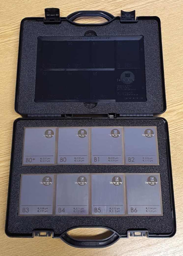
The theoretical model makes Ra exactly Rz over 4, and that clean relationship is where the folklore comes from. Real surfaces do not cooperate. Rz is a peak-to-valley measure, so it is dominated by the extremes that Ra was designed to average away. On a clean periodic turned profile the ratio does sit near 4. On a torn, smeared, or abrasively finished surface, 6 to 10 is ordinary, and one deep isolated scratch can push Rz past 15 times Ra while Ra barely moves. That is not measurement error, it is two parameters correctly reporting different things.
What Anodizing Does to the Number
Anodize does not smooth anything. It converts the outer skin of the part to oxide, replicating whatever was underneath and adding its own texture, so Ra measured after anodize is at or above what you measured before. Type II sulfuric coatings typically run 0.0002 to 0.001 in total thickness with roughly half growing outward from the original surface, and Type III hardcoat is thicker and more crystalline, so its effect on roughness is larger. The pre-treatment is often the real story: a caustic etch for a matte appearance attacks preferentially and can move a machined surface up by a large factor on its own. Three consequences follow. Anodize makes tool marks more visible, not less, because it strips the light-scattering smear and lays a uniform tint over the remaining topography. Growth is real and belongs in your pre-anodize target, which is what /resources/anodize-growth-calculator is for. And an Ra callout on an anodized part is ambiguous unless the drawing says whether it applies before or after coating. Most do not say. Ask in writing before you cut, because the two requirements can be a full ladder rung apart.
What the Print Is Really Asking For
Finish callouts are usually a proxy for a functional worry, and the proxy is often the wrong parameter for the worry. Reading through to the intent is what lets you push back intelligently instead of either eating the cost or shipping a part that passes inspection and fails in service.
- A sealing face is worried about leak paths, which are peaks, valleys, and lay, not an average. Rz or Rmax plus a specified lay direction says it properly. A blanket Ra can pass with a radial scratch straight across the seal.
- A fatigue-critical surface is worried about crack initiation sites, meaning deep isolated features. That is an Rz or Rmax concern, and it is why 7xxx parts in sustained tension deserve a peak-to-valley limit and not only an Ra number.
- A cosmetic surface is worried about how uniform it looks, which Ra does not measure at all. Two surfaces at identical Ra look completely different if the lay differs, and anodize amplifies the difference.
- A bonded or adhesive joint usually wants more roughness, not less. A tight Ra maximum on a bond face is often a copied note working against the design.
- A press fit or bearing bore is worried about the fit changing as high spots wear in. That is a bearing-ratio question, handled with a finish spec plus a fit callout, which is where /resources/tolerance-feasibility-checker earns its keep.
- A blanket 125 Ra note applied to every surface, including sawn edges and drilled hole bottoms, is a template rather than a requirement. Say so early, get a deviation on the surfaces that do not matter, and spend the money on the one that does.
The formulas are worth knowing exactly because they set a floor, and a floor tells you when the argument is over. If f squared over 32r already exceeds the print, no amount of tuning saves that combination of feed and nose radius, and you need a different radius, a different feed, or a different callout. But if the floor is 8 microinches and the part measures 80, the feed is not the problem and never was. Aluminum makes that mistake easy to fall into, because the failure modes that dominate the trace are built-up edge, a no-longer-sharp edge, runout, and deflection, and every one of them gets worse when you get gentle. Sharp polished tools, aggressive chip evacuation, measured runout, short tools, and enough chip thickness to actually shear will move the number further than any feed override. And read the callout before any of that: know whether the print wants an average, a peak, a lay, or just a template note somebody copied off the last drawing.
Frequently Asked Questions
What surface finish can you actually achieve on aluminum?
A general milling finish pass on aluminum delivers 32 to 125 uin Ra (0.8 to 3.2 um), and a dedicated light finish pass with sharp polished tooling and a rigid setup reaches 16 to 63 uin (0.4 to 1.6 um). Turning and boring reach the same 16 to 63 uin band, with 8 uin possible on a well-controlled machine. Below about 16 uin you generally leave milling for grinding, honing, lapping, or diamond turning.
How do I calculate the feed rate for a target Ra?
Use f = sqrt(32 x r x Ra), with everything in inches. For a 32 uin target (0.000032 in) with a 1/32 in nose radius, f = sqrt(32 x 0.03125 x 0.000032) = 0.0057 in/rev. That is a ceiling on feed, not a recommendation, because it assumes a perfect edge with zero runout and zero deflection. Plan to run below it and use /resources/surface-finish-predictor to account for the rest.
What is the difference between 125 Ra and 63 Ra?
125 uin (3.2 um) is the default machined finish that any competent finish pass produces, and it should carry no upcharge. 63 uin (1.6 um) generally requires one deliberate additional pass with a tool reserved for finishing. The real cost step is not between those two, it is at 32 uin, where a shop has to actively control tool condition, runout, and deflection and verify the result with a profilometer.
Why is my surface finish bad on 6061 aluminum?
Almost always built-up edge. 6061-T6 and T651 are soft at roughly 95 HB and ductile, so the chip pressure-welds to the rake face, blunts the edge, and periodically tears off across the finished surface. The fixes are a sharp polished uncoated, ZrN, or TiB2 tool, high helix and high positive rake, surface speed in the 800 to 3000 SFM range rather than backing off, aggressive chip evacuation, and enough feed per tooth that the actual chip after radial thinning stays thicker than the tool edge radius.
Is Rz always 4 times Ra?
No. The 4x relationship holds only for the idealized periodic scallop profile that the theoretical formula describes. Real machined surfaces commonly run 4 to 10 times, and a single deep scratch can push Rz beyond 15 times Ra while leaving Ra nearly unchanged. There is no valid fixed conversion, which is why a drawing calling out both an Ra and an Rz maximum taken from different tables can be impossible to satisfy at once.
Does anodizing improve surface finish?
No. Anodizing replicates the topography underneath it and adds its own, so Ra measured after anodize is at or above the pre-anodize value, and any caustic etch used for a matte appearance roughens the surface further. Anodize also makes tool marks more visible because it removes the light-scattering smear. Machine the finish you need before coating, account for growth of roughly half the coating thickness outward, and get the drawing to state whether the Ra callout applies before or after coating.
Cut to size, ready to finish
A good finish pass starts with plate that is flat and stress relieved
A finish pass only produces a uniform finish if it takes a uniform depth of cut. Plate that is bowed or not stress relieved makes radial engagement vary along the wall, which makes deflection vary, which lands directly on the trace. We ship DFARS domestic 6061-T651, 7075, 7050, and 5000 series plate cut to size with mill certs on every order, priced instantly.