
Why Your Aluminum Part Chatters, and Why It Is Almost Never the Alloy
By Celeborn
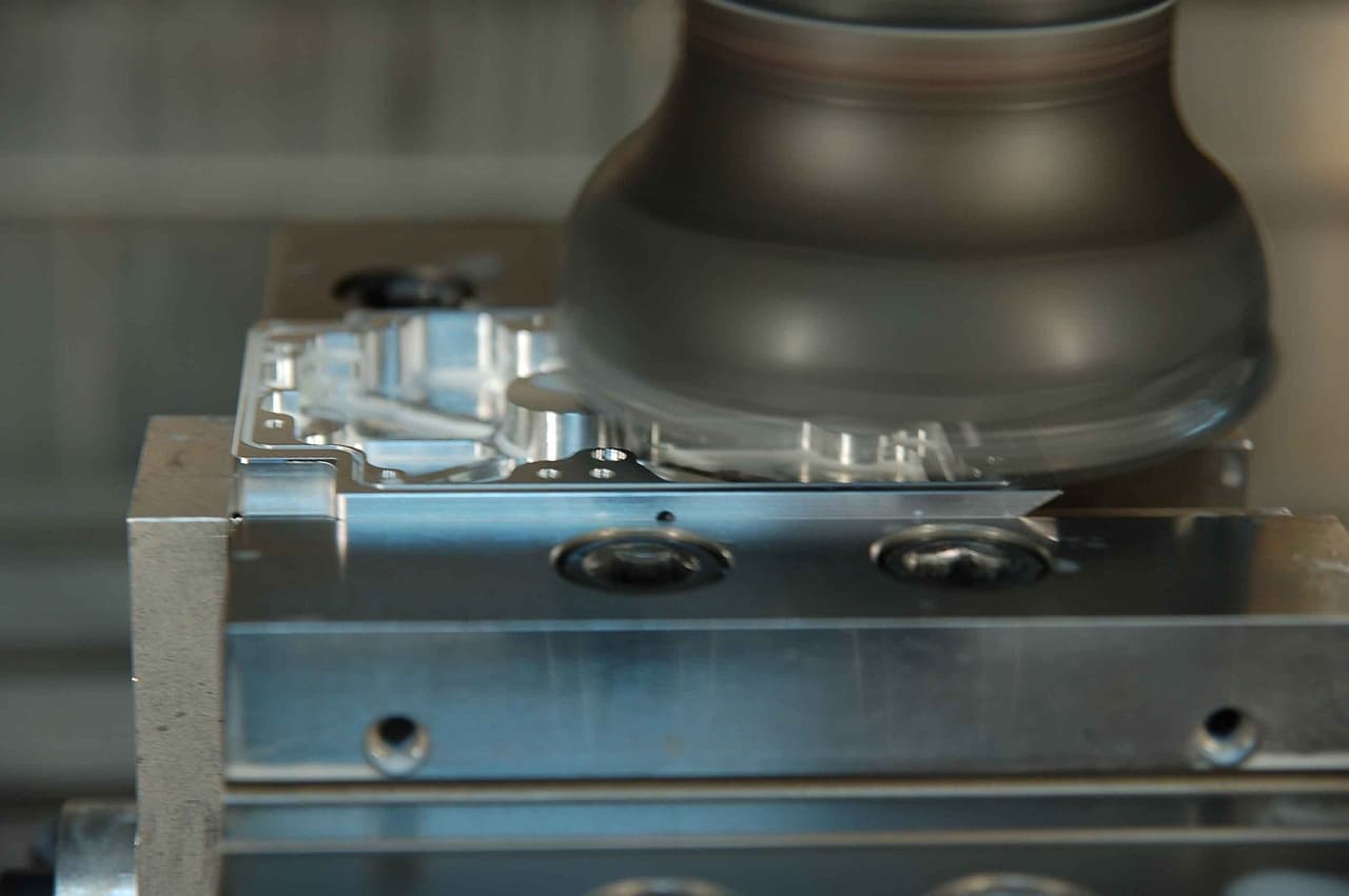
Search any machining forum for aluminum chatter and you will find fifty replies arguing about alloy. 6061 is gummy, 7075 cuts cleaner, somebody swears 7050 rings like a bell. Almost none of that explains chatter, because chatter is a stiffness and stability problem, and the stiffness of the aluminum is not the variable that is failing. The elastic modulus of these three alloys differs by about 4 percent. The stickout on your end mill probably differs by 100 percent between the setup that worked and the setup that screamed, and deflection scales with the cube of that number. This post walks the actual mechanics: the cantilever relation that governs tool deflection, the chip thinning factor that explains why light radial passes need more feed rather than less, what the alloy genuinely changes, and the ranked fix list that works in the order it is written.
In Short
- →The elastic modulus of 6061, 7075, and 7050 spans roughly 10.0 to 10.4 million psi, about 4 percent. For stiffness purposes the three alloys are the same material.
- →Tool deflection scales with the cube of stickout. Halving the overhang cuts deflection by 8x. Nothing else on the machine gives you that leverage.
- →What the alloy does change is force. 7075-T651 has roughly 1.6 times the shear strength of 6061-T6, so the same cut pushes the tool about 60 percent harder while the tool is exactly as stiff as before.
- →Light radial cuts need MORE feed per tooth, not less. At 10 percent radial engagement the chip thinning factor is 1.667, so a programmed 0.004 in per tooth is really cutting 0.0024 in.
- →Chatter itself is a dynamic stability problem. No web calculator, including ours, can hand you a guaranteed chatter-free RPM without a tap test on your specific tool, holder, and spindle.
The Stiffness Argument Is Already Over
Stiffness of the workpiece material enters the problem through the elastic modulus, E. Published values for these three alloys sit within a few percent of each other: 6061-T6 at about 68.9 GPa, which is 10.0 million psi, 7075-T651 at about 71.7 GPa or 10.4 million psi, and 7050-T7451 at about 70.3 GPa or 10.2 million psi. Sources do disagree at the second digit. MatWeb and ASM list 7075 at 71.7 GPa while MakeItFrom rounds both 7075-T651 and 7050-T7451 to 70 GPa, so treat the honest range as 10.0 to 10.4 million psi across the family. That total spread is about 4 percent. There is no setup in which a 4 percent difference in workpiece modulus decides whether a cut is stable, and the tool is not made of aluminum anyway. Solid carbide runs around 87 million psi, roughly 8.5 times the modulus of any plate you are cutting. Published values for cemented carbide range from about 80 to 92 million psi depending on cobalt content, so treat 87 as a working number. The tool is still usually the most flexible element in the loop, and that is a geometry problem, not a material problem.
10.0e6 psi
6061-T6 elastic modulus (68.9 GPa)
MatWeb / ASM Aerospace Specification Metals
10.4e6 psi
7075-T651 elastic modulus (71.7 GPa)
MatWeb / ASM
10.2e6 psi
7050-T7451 elastic modulus (70.3 GPa)
MatWeb, MakeItFrom rounds to 70 GPa
Elastic modulus in million psi. The bars are supposed to look identical
The Cube Law: Where Your Rigidity Actually Went
An end mill in a holder is a cantilever beam. A radial cutting force at the tip deflects the tip by an amount that depends on the force, the unsupported length, the material stiffness, and the cross-section. The relation is the standard end-loaded cantilever result, and the second moment of area for a round section brings in the fourth power of diameter. Two exponents do all the work here. Deflection goes with length cubed, and inversely with diameter to the fourth. Everything else is linear. That is why a 3/8 inch tool at the same overhang deflects roughly 3.2 times as much as a 1/2 inch tool, and why pulling a half inch of overhang out of a setup is worth more than every other change you can make in five minutes.
End-loaded cantilever deflection
delta = F L^3 / (3 E I) where I = pi d^4 / 64 Worked example, 1/2 in solid carbide, 2.0 in stickout, 100 lbf radial: I = pi (0.500)^4 / 64 = 0.003068 in^4 3 E I = 3 (87,000,000) (0.003068) = 800,738 lb-in^2 delta = 100 (2.0)^3 / 800,738 = 0.00100 in
= 0.001 in of tip deflection at 2.0 in stickout. Same force at 4.0 in stickout gives 0.0080 in, exactly 8x.
- delta
- Tip deflection, inches
- F
- Radial cutting force at the tool tip, lbf
- L
- Stickout, from the face of the holder to the tool tip, inches
- E
- Elastic modulus of the tool. Solid carbide is about 87e6 psi, HSS about 30e6 psi
- I
- Second moment of area, in^4. Scales with d^4, so diameter dominates
- d
- Effective diameter. Use the flute core, not the cutting diameter, for a fluted length
Deflection vs L/D for a 1/2 Inch Carbide End Mill
Here is the same calculation swept across the length to diameter ratios people actually run, at a fixed 100 lbf radial load. The first column is the idealized solid shank. The second applies the 0.8 diameter flute correction, which is closer to what a fluted end mill really does. Look at the jump from L/D 4 to L/D 8: the number goes up by a factor of 8 with no change in tool, alloy, RPM, or coolant.
Flute-corrected tip deflection at 100 lbf, in thousandths of an inch
| L/D | Stickout (in) | Solid shank delta (in) | Flute-corrected delta (in) | Relative to L/D 4 |
|---|---|---|---|---|
| 2 | 1.0 | 0.00012 | 0.00030 | 0.13x |
| 3 | 1.5 | 0.00042 | 0.00103 | 0.42x |
| 4 | 2.0 | 0.00100 | 0.00244 | 1.00x |
| 5 | 2.5 | 0.00195 | 0.00476 | 1.95x |
| 6 | 3.0 | 0.00337 | 0.00823 | 3.38x |
| 8 | 4.0 | 0.00799 | 0.01951 | 8.00x |
What the Alloy Does Change: Force, Not Stiffness
The alloy is not irrelevant. It is just acting on the numerator, not the denominator. Cutting force scales with the material's resistance to shear, and there the three alloys are genuinely different. Published shear strength runs about 210 MPa or 30 ksi for 6061-T6, about 310 MPa or 45 ksi for 7050-T7451, and about 330 MPa or 48 ksi for 7075-T651. That makes 7075 roughly 1.6 times as hard to shear as 6061. Take the same tool, the same stickout, the same chip load, and move from 6061 to 7075, and radial force rises by something in the neighborhood of 50 to 60 percent while the stiffness of the tool does not move at all. Deflection rises by the same 50 to 60 percent. That is a real effect and it is worth planning around, but notice the scale: a 1.6x force penalty is completely erased by pulling stickout from 2.0 inches down to 1.5 inches, which buys back 2.37x.
Alloy penalty vs stickout reduction
force ratio 6061 to 7075 = 48 ksi / 30 ksi = 1.60x more deflection (1.57x on the unrounded 330 / 210 MPa values) stickout 2.0 in to 1.5 in = (2.0 / 1.5)^3 = 2.37x less deflection net effect of doing both = 1.60 / 2.37 = 0.68x
= Shortening the tool by half an inch more than pays for the entire alloy change. This is why the forum arguments are misdirected.
- 1.60x
- Deflection penalty for switching 6061 to 7075 at identical parameters
- 2.37x
- Deflection credit for a 0.5 inch shorter tool at 1/2 inch diameter
- 0.68x
- Net 32 percent less deflection in 7075 than you started with in 6061
| Alloy | Shear strength | Force vs 6061 | Practical consequence |
|---|---|---|---|
| 6061-T6 / T651 | 210 MPa (30 ksi) | 1.00x | Lowest force, but soft and prone to built-up edge and rubbing |
| 7050-T7451 | 310 MPa (45 ksi) | ~1.48x | Higher force, cuts clean, thick sections carry residual stress |
| 7075-T651 | 330 MPa (48 ksi) | ~1.57x | Highest force, best chip break, least forgiving of a marginal setup |
Radial Chip Thinning: Why Light Cuts Need More Feed
The single most common self-inflicted chatter cause we see is a shop that correctly decides to take a lighter radial cut and then incorrectly leaves the feed alone or reduces it. When radial engagement is less than half the tool diameter, the tool never reaches full chip thickness. The chip is thinner than the programmed feed per tooth by a geometric factor, and if you do not compensate, you drop below the minimum chip thickness for the cutting edge to shear cleanly. Below that threshold the edge plows and rubs instead of cutting. Rubbing means friction, heat, an unstable force that varies with edge radius rather than with chip load, and a tool that is being excited rather than loaded. Chatter, poor finish, and short tool life all follow from the same mistake.
Radial chip thinning factor
RCTF = 1 / sqrt( 1 - (1 - 2 ae / D)^2 ) programmed fz = desired chip thickness x RCTF Example, 1/2 in tool, ae = 0.050 in (10 percent of D), target 0.004 in chip: 1 - 2(0.050)/0.500 = 0.800 RCTF = 1 / sqrt(1 - 0.640) = 1 / 0.600 = 1.667 programmed fz = 0.004 x 1.667 = 0.0067 in per tooth
= At 10 percent radial engagement you must program 1.667x the feed per tooth to get the chip you intended. Leave it at 0.004 and you are actually cutting 0.0024 in and probably rubbing.
- ae
- Radial depth of cut, also called radial engagement or stepover, inches
- D
- Tool cutting diameter, inches
- RCTF
- Multiplier on feed per tooth. Exactly 1.000 at ae = 0.5D, and it only grows from there
- fz
- Feed per tooth, inches
| Radial engagement ae | ae / D | RCTF | Programmed fz for a 0.004 in chip |
|---|---|---|---|
| 0.250 in | 0.50 | 1.000 | 0.0040 in |
| 0.200 in | 0.40 | 1.021 | 0.0041 in |
| 0.150 in | 0.30 | 1.091 | 0.0044 in |
| 0.125 in | 0.25 | 1.155 | 0.0046 in |
| 0.100 in | 0.20 | 1.250 | 0.0050 in |
| 0.075 in | 0.15 | 1.400 | 0.0056 in |
| 0.050 in | 0.10 | 1.667 | 0.0067 in |
| 0.025 in | 0.05 | 2.294 | 0.0092 in |
| 0.010 in | 0.02 | 3.571 | 0.0143 in |
Chatter Is Not Deflection. It Is a Stability Problem
Deflection is static. Push the tool with a steady force and it bends by a predictable amount. Chatter is dynamic and it is a feedback loop, technically regenerative self-excited vibration. The cutting edge leaves a wavy surface. The next tooth cuts into that wave, so the chip thickness varies, so the force varies, so the tool vibrates more, and the new wave it leaves may be out of phase with the last one in a way that amplifies. Whether it amplifies or decays depends on the phase relationship between the tooth passing frequency and the natural frequency of the whole flexible loop: spindle, holder, tool, part, fixture, machine. That is what a stability lobe diagram plots, and the stable pockets are narrow, alternating, and specific to your exact assembly.
- The dominant natural frequency is a property of your assembly, not the alloy. A 1/2 inch carbide end mill in a decent holder typically rings around 1,500 to 4,000 Hz, but the only way to know your number is to measure it.
- A tap test measures it. You strike the tool tip with an instrumented hammer, capture the response with an accelerometer, and take the frequency response function. The peaks are the modes, and the width of a peak tells you the damping. Commercial systems do this in minutes.
- Tooth passing frequency in Hz is RPM times the number of flutes divided by 60. At 12,000 RPM with 3 flutes that is 600 Hz. A tool that rings at 2,000 Hz is nowhere near its high-speed stability lobe at 600 Hz.
- To land in the wide high-speed lobe you would need 60 times 2,000 divided by 3, or 40,000 RPM. Most shops do not have that spindle, which is why in the low-speed region the lobes are narrow and RPM tweaking feels like guesswork. It genuinely is, without measured data.
- Variable helix and variable pitch tools break up the regeneration. Unequal tooth spacing makes each tooth meet the previous wave at a different phase, which frustrates the feedback loop. This is why they often fix chatter that no parameter change would.
- Anyone selling a universal chatter-free RPM from three inputs is selling a guess. Our /resources/tool-deflection-chatter-calculator gives you deflection, tooth passing frequency, and where you sit against a typical modal range. It cannot give you your actual modal frequency, because that requires hitting your tool with a hammer.
Sometimes It Is Not the Tool. It Is the Part
Before you buy a shrink-fit holder, decide which thing is actually ringing, and frequency is the tell. A chattering tool leaves fine, tight, regularly spaced marks at a high pitch, often 1 to 4 kHz. A thin unsupported part or a tall soft fixture rings in the hundreds of hertz and leaves coarser marks that follow the unsupported geometry rather than the toolpath. If the marks move when you move the clamps, it is the part. If the pitch changes when you change stickout, it is the tool. A wall 0.080 inch thick and 3 inches tall will not be saved by any toolholder. It needs support, a lighter radial cut, or extra wall left on until the final pass.
The Ranked Fix List
Work this list in order. The ordering is not a preference, it is a ranking by leverage per dollar and per minute. Most shops start at the bottom, spend a day fiddling with RPM overrides, and never get to the top.
Fix chatter in this order
- 1
Shorten the stickout
Free, 8x per halving
Cube law. Pull the tool up to the minimum overhang that clears the part and the fixture, and pick a stub length instead of long reach. This one change outweighs everything below it.
- 2
Cut radial depth, raise feed per tooth
Free, force down 2 to 4x
Drop ae to 0.10 to 0.20 of D and multiply feed per tooth by the RCTF above. Lower peak radial force, thicker chip. Add axial depth back to hold the removal rate.
- 3
Get a stiffer tool geometry
Tool cost, up to 2 to 3x
A necked or tapered tool keeps full diameter up in the holder and narrows only where clearance is needed. Since I scales with d^4, that full-diameter section is worth far more than it looks.
- 4
Improve the holder
$200 to $1,500
Shrink-fit or hydraulic beats a side-lock holder on runout, balance, and damping. Hydraulic adds real damping, which widens the stable region instead of just shifting it.
- 5
Check runout with an indicator
Free, 3 minutes
0.001 inch of TIR on a 2 flute tool makes one tooth cut 0.005 inch and the other 0.003 inch on a nominal 0.004 inch chip load. That is a plus or minus 25 percent force swing at spindle frequency.
- 6
Fix the workholding
Fixture time
Support the part where it is thin: soft jaws, a toe clamp, a mid-span support, or low-melt fill. If the marks change when the clamps change, this is your real problem.
- 7
Change flute count or tool style
Tool cost
Variable helix and variable pitch disrupt the regeneration. Fewer flutes leaves more chip room in aluminum. More flutes raises tooth passing frequency, which sometimes lands a stable pocket.
- 8
Only now touch the RPM
Free, low odds
Without a tap test you are hunting narrow lobes blind. Try plus or minus 10 to 15 percent in steps and listen. Write down what works, because it will not transfer to another tool.
How This Shows Up in Surface Finish
Keep these two measurements separate when you diagnose a part. A stable cut has a finish set almost entirely by feed per tooth and the corner or nose radius of the tool. An unstable cut has a finish set by vibration amplitude, which can be an order of magnitude worse and which does not improve when you slow the feed. So if you reduce the feed and the finish gets worse, that is diagnostic: you were already chip thinning yourself into a rub. For the theoretical number on a stable cut, /resources/surface-finish-predictor computes achievable Ra from feed and nose radius, and /resources/surface-finish-converter handles the unit conversions between Ra, Rz, RMS, and CLA when the drawing and your gage disagree.
| Symptom | Likely cause | First thing to change |
|---|---|---|
| Fine, tight, regular marks, high pitched squeal | Tool chatter, 1 to 4 kHz range | Shorten stickout, then reduce ae and raise fz |
| Coarse marks, low growl, worse near thin walls | Part or fixture ringing, hundreds of Hz | Support the part, lighter radial pass |
| Finish gets worse when you slow the feed | Chip thinning below minimum chip thickness | Apply RCTF and raise feed per tooth |
| Marks repeat once per revolution | Runout or a single high tooth | Indicate the tool, check the holder taper and the collet |
| Good finish, wrong dimension after unclamping | Residual stress in the plate, not vibration | Rough both sides, stress relieve, revisit fixturing |
| Smeared, torn, built-up surface in 6061 | Rubbing and built-up edge, not chatter | Sharper polished tool, raise chip load, more coolant |
A Note on Buying Stock That Does Not Fight You
One purchasing variable does touch this: the blank. A corner that is 0.060 inch oversize forces a heavier first pass than you planned, and a bowed blank does not clamp flat, so the part is preloaded before the cutter arrives. Cut-to-size blanks held to a tight thickness and squareness window let you plan the first pass instead of reacting to it. That is a small effect next to the cube law, and we will not pretend otherwise, but it is free if you buy the blank right the first time.
Two exponents explain most of what happens in an aluminum cut. Deflection scales with stickout cubed and inversely with diameter to the fourth, and everything else in the setup is roughly linear. Against those exponents, a 4 percent spread in elastic modulus between 6061, 7075, and 7050 is noise. The alloy does raise cutting force, meaningfully so, at about 1.6 times the shear strength going from 6061 to 7075, but a half inch of stickout reduction on a 1/2 inch tool buys back 2.37x and wins that argument outright. Then there is the part that is not static at all: chatter is a regenerative stability problem whose stable pockets depend on a modal frequency you have to measure with a tap test, not calculate from a web form. So work the list in order. Shorten the tool, drop the radial engagement and raise the feed per tooth to match the chip thinning factor, get the reach out of the tool geometry, then the holder, then the runout, then the fixture. Touch the RPM last, and be honest that you are guessing when you do.
Frequently Asked Questions
Why does my end mill chatter in aluminum?
In nearly every case the cause is too much stickout combined with too much radial engagement. Tool tip deflection scales with the cube of the unsupported length, so a tool at 8 times diameter overhang deflects 8 times as much as the same tool at 4 times diameter under the same load. Shorten the stickout to the minimum that clears the part, then cut radial depth to 10 to 20 percent of the tool diameter and raise feed per tooth by the chip thinning factor. Change RPM last, because without a tap test you are guessing at narrow stability lobes.
Does 7075 chatter more than 6061?
Not because it is stiffer, because it is not. The elastic modulus of 6061, 7075, and 7050 all fall between roughly 10.0 and 10.4 million psi, a spread of about 4 percent. What 7075 does is raise cutting force: its shear strength is about 48 ksi against about 30 ksi for 6061-T6, roughly 1.6 times. Higher force on an equally stiff tool means about 60 percent more deflection at identical parameters, so a marginal setup that survived in 6061 can fail in 7075. The fix is the setup, not the alloy.
How do I calculate end mill deflection?
Use the end-loaded cantilever relation, delta equals F times L cubed divided by 3 E I, where I equals pi d to the fourth over 64. For a 1/2 inch solid carbide end mill at 2.0 inch stickout under 100 lbf of radial force, I is 0.003068 in to the fourth, E is about 87 million psi for carbide, and the tip deflects about 0.001 inch. Use the flute core diameter rather than the cutting diameter for the fluted portion, typically 0.75 to 0.85 of the cutting diameter, which increases the result by roughly 2 to 3 times.
Should I feed faster or slower with a light radial cut?
Faster, in feed per tooth. Below half the tool diameter of radial engagement the chip is geometrically thinner than the programmed feed per tooth by the radial chip thinning factor, which equals 1 over the square root of 1 minus the quantity 1 minus 2 ae over D, squared. That factor is exactly 1.000 at 50 percent engagement and 1.667 at 10 percent engagement. Program 0.004 inch per tooth at 10 percent engagement and the tool is actually cutting 0.0024 inch, which is often below the minimum chip thickness, so the edge rubs instead of shearing.
What is a tap test and do I need one?
A tap test measures the frequency response of your assembled tool, holder, and spindle by striking the tool tip with an instrumented hammer and recording the response with an accelerometer. The result gives you the dominant natural frequencies and the damping, which is what you need to build a stability lobe diagram and find genuinely stable spindle speeds. You need one if you are chasing the last 20 percent of metal removal rate on a repeated production job. For one-off work, shortening the tool and correcting chip thinning gets you most of the way there without any instrumentation.
How do I tell if the tool is chattering or the part is ringing?
Listen to the pitch and look at the mark spacing. A tool chattering is high pitched, usually 1 to 4 kHz, and leaves fine, tightly and regularly spaced marks. A thin part or a tall fixture rings much lower, in the hundreds of hertz, with coarser marks that follow the unsupported geometry rather than the toolpath. Practical test: if the marks change when you move the clamps, it is the part. If the sound changes pitch when you change the stickout, it is the tool.
Check Your Stickout
Stop guessing at stickout.
Our deflection and chatter calculator runs the cantilever math, the chip thinning factor, and your tooth passing frequency together so you can see which change actually buys you stability. When you are ready for stock, quote 6061, 7075, or 7050 plate cut to your blank size in under 60 seconds, certs included.